Cat 6 Poe Camera Wiring Diagram / Lorex Ip Camera Wiring Diagram - Wiring Diagram / Brown & white pin 8:. Poe camera wires to cat 5/6 connector (t568b) for these camera models. I plan to use 2 cameras on the cat6 cable without any adapters or switch. To properly read a wiring diagram, one offers to learn how typically the components. Ip needs 2 pairs of wire to communicate with the nvr. 8 pin rj45 8p8c male connector at the cable.
The camera uses one pair to talk to the nvr wire #1 and #2. As external power doesn't needed in poe ip cameras, therefore connect only the cameras through poe via cat5 / cat 6 cables. Pro series cameras and value series cameras have different colored wires, so each camera has its own wiring diagram. Cat 5/cat 6 poe cameras are first plugged into a poe switch/poe injector or network video recorder (nvr) with poe ports and a network router, and then the security camera will be up and running. I of course know what the standard rj45 a and b type pinouts are but the problem is, when you open up the camera or strip some of the outer jacket from the cable, amcrest is not using standard colors for the wires to the rj45.
Get Ptz Controller Wiring Diagram Sample from worldvisionsummerfest.com To connect a new connector (rj45 jack) to the hikvision ip camera refer to the diagrams below. Poe outdoor cam rj45 cable pinouts. When i cut of the female sockets i discovered that there were only six cat5e wires instead of the four twisted pairs. Cat 6 poe camera wiring diagram / dahua ip camera color code pinout for the ethernet ip megapixel cameras and software solutions cctvforum com. I have two lorex ip cameras (model # mcnb3143) with damaged cat5e sockets. Hikvision ip camera rj45 pin out wiring diagram cornick poe details cruze cctv injectors cameras installation and options network repair the cable on a simplified ethernet online how to wire learn com cat 5 crossover power over switch faqs lorex works kintronics connect nvr surveillance security types 12 volt. Cat5e / cat6 ethernet cables for ip home security systems purchase additional runs of cat5e / cat6 cables to wire your home ip security system. Otherwise, the arrangement won't function as it ought to be.
Ethernet rj45 connection wiring and cable pinout diagram pinouts ru from pinouts.ru.
It consists of directions and diagrams for different varieties of wiring strategies as well as other products like lights, windows, and so on. 8 pin rj45 8p8c male connector at the cable. I have two lorex ip cameras (model # mcnb3143) with damaged cat5e sockets. Poe camera wires to cat 5/6 connector (t568b) for these camera models. This is what worked for me. Pins 2 and 3 transmit data to and from the camera. Cat 6 poe camera wiring diagram : I plan to use 2 cameras on the cat6 cable without any adapters or switch. As external power doesn't needed in poe ip cameras, therefore connect only the cameras through poe via cat5 / cat 6 cables. Cat 5/cat 6 poe cameras are first plugged into a poe switch/poe injector or network video recorder (nvr) with poe ports and a network router, and then the security camera will be up and running. The camera uses one pair to talk to the nvr wire #1 and #2. This article explain how to wire cat 5 cat 6 ethernet pinout rj45 wiring diagram with cat 6 color code , networks have become one of the es. Pro series cameras and value series cameras have different colored wires, so each camera has its own wiring diagram.
To properly read a wiring diagram, one offers to learn how typically the components. **please do not use this diagram to create a pinout for a separate power source for the simplified poe cameras. The nvr uses another pair to talk to the camera wire #3 and #6. Power over ethernet wiring diagram category 5 cable ip camera png 800x484px area. The six wires on the camera are orange, yellow, green, purple, gray, blue, and brown.
DIY PoE injector for 10/100M Ethernet - Circuits DIY from www.circuitsdiy.com As external power doesn't needed in poe ip cameras, therefore connect only the cameras through poe via cat5 / cat 6 cables. The nvr uses another pair to talk to the camera wire #3 and #6. Collection of poe camera wiring diagram. In most cases you run your video and power to and from the camera on the same cat5 or cat6 wire, assuming you are using a poe (power over ethernet) power source such as a poe injector or poe switch. Cat 6 poe camera wiring diagram / dahua ip camera color code pinout for the ethernet ip megapixel cameras and software solutions cctvforum com. Cat 6 poe camera wiring diagram : Purchase lengths of cable up to 300 feet long. The camera uses one pair to talk to the nvr wire #1 and #2.
**please do not use this diagram to create a pinout for a separate power source for the simplified poe cameras.
Cat 6 poe camera wiring diagram : Poe outdoor cam rj45 cable pinouts. You can use passive poe splitter and poe injector and the wire length can be 130 feet (40 meter). Brown & white pin 8: The camera uses one pair to talk to the nvr wire #1 and #2. I need to install new sockets but don't know the wiring diagram. Here is my understanding of ip cameras and cat5: To get a better idea, the ethernet ip security camera wiring diagram is shown below. Cat5 enhanced(cat5e) replaced the traditional cat5 cable and introduced speeds up to ten times faster than cat5 cable. Pins 2 and 3 transmit data to and from the camera. Each component ought to be placed and connected with different parts in particular way. I have two lorex ip cameras (model # mcnb3143) with damaged cat5e sockets. Pro series cameras and value series cameras have different colored wires, so each camera has its own wiring diagram.
Collection of poe camera wiring diagram. Otherwise, the arrangement will not function as it should be. Cat 6 poe camera wiring diagram / to get a better idea, the ethernet ip security camera wiring diagram is shown below. Reliable network with ethernet cat6 wiring. The six wires on the camera are orange, yellow, green, purple, gray, blue, and brown.
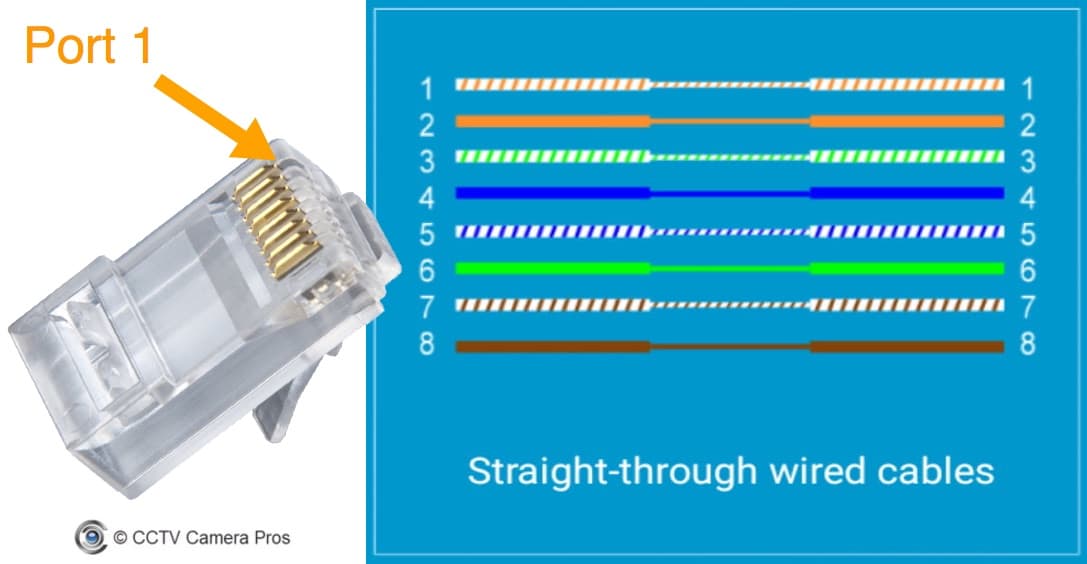
CAT-5 Wiring Diagram | Crossover Cable Diagram from www.cctvcamerapros.com Green & white pin 4: The camera uses one pair to talk to the nvr wire #1 and #2. Brown & white pin 8: Here is my understanding of ip cameras and cat5: The simplest way to wire a poe camera is to connect it directly to a poe nvr. Reliable network with ethernet cat6 wiring. If you do decide to go the cat6 route there will be a few more options. When i cut of the female sockets i discovered that there were only six cat5e wires instead of the four twisted pairs.
To get a better idea, the ethernet ip security camera wiring diagram is shown below.
Lorex offers additional runs of ethernet cables to accommodate security system installations that require extra cat5e / cat6 wiring. Pin 1, 2, 3, 6 are for data transfer while pin 4, 5, 7, 8 are for poe. Each part should be placed and connected with different parts in specific way. 8 pin rj45 8p8c male connector at the cable. To properly read a wiring diagram, one offers to learn how typically the components. Collection of poe camera wiring diagram. Otherwise, the arrangement won't function as it ought to be. As external power doesn't needed in poe ip cameras, therefore connect only the cameras through poe via cat5 / cat 6 cables. Each component ought to be placed and connected with different parts in particular way. Purchase lengths of cable up to 300 feet long. The six wires on the camera are orange, yellow, green, purple, gray, blue, and brown. Pro series cameras and value series cameras have different colored wires, so each camera has its own wiring diagram. Pin 1, 2, 3, 6 are for data transfer while pin 4, 5, 7, 8 are for poe power supply.